 Map")
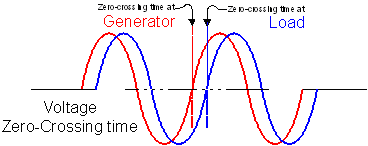
 Transmission Use Evident from Cycle TimingFeb 22, 2005 David Tuck, energypulse.net A three-phase transmission line is an electrical model of a rotating shaft. A drive shaft under heavy load will exhibit a small amount of torsion between the power head and the load end. Similarly, the load end of an electrical line will lag the generation end by a small but measurable amount. The familiar sine wave is representative of an AC voltage, and if an event recorder monitoring voltage captures the exact time it rises through zero at the generator while another event recorder captures the time at a load substation, then both times can be compared (see Figure 1).
Figure 1: Measure Zero-Crossings The difference between the two times won’t translate directly to MWhs of flow, but it will be a relative measurement based upon actual energy flow, line capacity, and distance. The time difference will convey a wealth of system information when used in conjunction with voltage measurements taken from the other substations in the neighborhood.
In this way, this article proposes to use voltage cycle timing to determine relative transmission line loading. It is based on the time differences in measured voltage events (zero-crossings of a selected phase) at multiple locations across a synchronized system. By accepting cycle timing as a metric, reliability coordinators would be able to quantify power flow and transmission line strength by comparing single instantaneous value per voltage level from different substations. Furthermore, readings taken anywhere within the interconnected area would be meaningful everywhere else regardless of region, control area, or state borders.
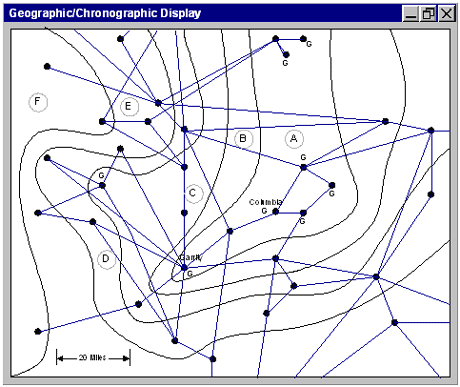
To make sense of this, a precision event recorder capable of time-stamping voltage events with microsecond accuracy must be placed in every substation at every voltage level. Each recorder, synchronized to Universal Time via GPS, reports the time-stamp of selected cycles and submits them to a central web server. The server receives and stores the information into a time-structured database. Time, as the subject of the metric, will be used in interesting ways. Displays to Represent Area Timing The gathered information, once received and stored, could be displayed in a geographic map of substations and transmission lines. The chronographic aspect could be shown as zones of difference where contour lines clearly indicate bands of common cycle time difference. See Figure 2 below where generator substations (labeled ‘G’) lead other areas in bands of time difference. Visualize the view to be similar to a contoured map showing elevation—in this case the generators are the peaks and high plateaus while loads are ‘downhill’, or at least down sloping, to valleys. The actual course taken by the energy flow can be visualized as elevation drop along transmission lines of the map, which is actually represented by time difference through the many contour lines between substations. Figure 2: Geographic/Chronographic Display In this view, the transmission line between Garrity and Columbia is intersected with no time boundary contour lines while there are 3 contours on the line going South of Garrity. This reveals that relatively light loading exists between the two generators, but relatively heavy loads reside to the South.
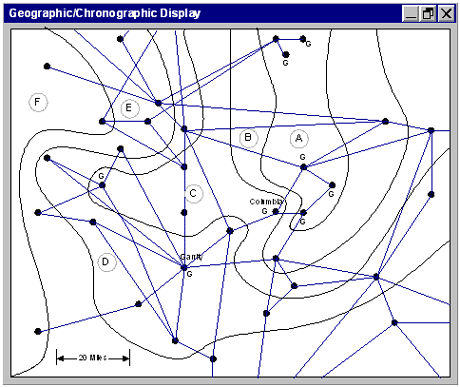
The display works because a time-stamp measurement taken when voltage at the source crosses zero always occurs ahead of the sink by a measurable amount. What will be the time measurements where there are numerous generators and loads distributed over the map? The answer, obviously, is that the zones with greater generation will lead zones with greater load. Due to the physics of the electric system, all components will quickly seek their place in time, and although still synchronized, will exhibit time differences that will indicate the actual direction the energy flows. Visibility of Instability Today, the electric industry achieves and maintains 60Hz synchronization across the national power grid using sophisticated methods involving generator control equipment. However, the grid itself is far from being rock-solid stable. It is influenced by every change of load and every change in generation. The energy behind the generators tries to speed-up rotational frequency while the load tries to slow it down—all being held in check by control equipment. In fact, the entire interconnected grid exactly matches generation to load. Inadvertent differences are manifested in deviations of frequency away from exact 60Hz. Too much generation, the frequency rises above 60Hz—too much load, it drops below 60Hz. With the grid operating like a roiling sea of turmoil, shifting contours will highlight oscillations. Consider Figure 3 in relationship to Figure 2. If these two displays alternated separated by one or two seconds, it would reveal a struggle between Garrity and Columbia generators. This struggle would indicate system instability and consuming excess generator fuel, capacity, and causing a certain amount of needless transmission losses.
Figure 3: Contour Shape Fluctuations Evident Timing Reference This system is dependent upon all substation sites to be precisely time-synchronized together. Each site can do this using the timing features of the Global Positioning System (GPS), which produces a synchronized and accurate timing pulse to sub- microsecond accuracy to Universal Time regardless of world location. Once synchronized, substation recorders can measure their time and report the difference between it and the reference.
To establish a universal reference, NERC could simply state that there shall be exactly 60 pulses per second with the first pulse arriving exactly at the 1-second mark. This is not really a new concept; NERC has always worried about frequency. But to establish a true reference, there must be a start stating that this particular cycle is the beginning, and from now on, all cycles will be based from it. Thanks to the wandering nature of frequency, it is well known that such a reference could lead or lag its intended place in time by multiple seconds.
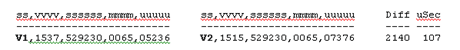
Another possibility is to allow the reference to be ‘in the clock of the beholder’. In other words, a control area could monitor every substation inside itself and declare the reference to be the leading measurement, and all other measurements would be shown as time offsets from it. Therefore, the leading generator has zero time difference and each other substation lags it by a certain number of microseconds. Since there are approximately 16,667 microseconds per cycle, each degree of generator shaft rotation is 46.296 microseconds. This measurement accuracy is well within measuring capability of today’s synchro phasors and high-speed event recorders, and would certainly provide adequate time bands from which to build map contours. So Many Measurements, So Little Time The author has constructed event recorders with fast enough time-stamping capability to verify the concepts purported herein. The table below is a sample of recently captured time-stamps from two substations separated by an estimated 18 miles (where ss=substation code, vvvv=voltage, ssssss=Garmin seconds, mmmm=milliseconds, and uuuuu=number of 1/20 microseconds): Although these measurements are anecdotal, the author believes that the 107 uSec lag of substation V2 behind V1 indicates a robust flow towards V2. (If the distance between the two substations is 18 miles as believed, the voltage waveform should exhibit a difference of about 96 uSecs accounting for the speed of light for the voltage waveform to travel the distance. The fact that it took 11 uSec longer indicates a certain amount of loading on the line.)
The information that would have been sent across a wide area network for this single comparison would have amounted to a raw 25 characters per measurement. Inside the central processor’s data storage, the time value for each substation could be stored as the raw time reading and a difference value. V1’s difference would store 0 (because it is the leading sub) and V2’s difference would store 107 (because it is lagging the reference by 107 microseconds). Naturally, there could be 60 of these stamps per second, and the database could store the integrated difference as a single ‘average over a second’ integer. Or, if desired, it could store 60 seconds as an integrated ‘average over a minute’ integer. And, by extension, hourly averages can be derived as well. For making historical records, all the above may be desirable, and after a few months of history is correlated with integrated MWh readings, future hours could be forecast. Conclusion: A New Generation of Metering Equipment This new time-stamping event recording meter along with its data accumulator and contour map displays (patent pending) as proposed in this article would be an inexpensive step in allowing all electric providers to make lower voltage measurements and yet easily see the flow of system load as a relative picture on a geographic/chronographic display. Such a meter can be cheaply placed in a substation, connected to a voltage device on a single phase, to a GPS receiver, and to the Internet. It could transmit time measurements only, or add other available features with small incremental costs. A web server at the control center could handle the data accumulation and storage with traditional time-oriented database applications and new software designed to retrieve, sort, and replay captured events. When future hour forecasts are made, E-Tag and pending schedule approvals could be easily tested—just ensure that no Point-of-receipt to Point-of-delivery path segments crosses too many contour lines!
Reliability centers would desire this type of information to monitor system health in real time. Marketers and power agents would desire this type of information to help them schedule energy across transmission paths that exhibit few contour lines crossing the path. The metric information from around the nation could be sold to subscribers where they may view regions in a real-time or historically integrated history display map. Such may help simplify decisions of energy scheduling and help open competition in the electric industry.
l |
Email this page to a friend
If you speak another language fluently and you liked this page, make
a contribution by translating
it! For additional translations check out FreeTranslation.com
(Voor vertaling van Engels tot Nederlands)
(For oversettelse fra Engelsk til Norsk)
(Для дополнительных
переводов проверяют
FreeTranslation.com )